


Language
Battery Energy Storage Systems of 1 MWh and Above for Photovoltaic Power Plants
Sep 02, 2026
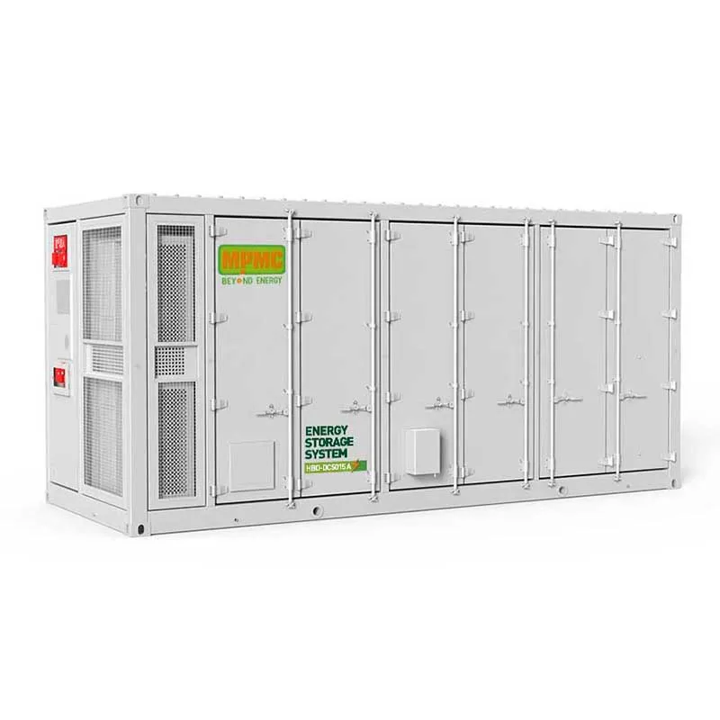
Storage added to a photovoltaic plant is not simply capacity attached to generation. It changes what the plant can offer — a firmed output, a shifted delivery profile, or a response service — and each of those is a different sizing problem with a different control requirement. Establishing which the project is selling comes before selecting equipment. MPMC POWERTECH CORP., established in 2008 and headquartered in Shanghai Pudong, publishes a stationary HBD-A range reaching this capacity in a single unit.
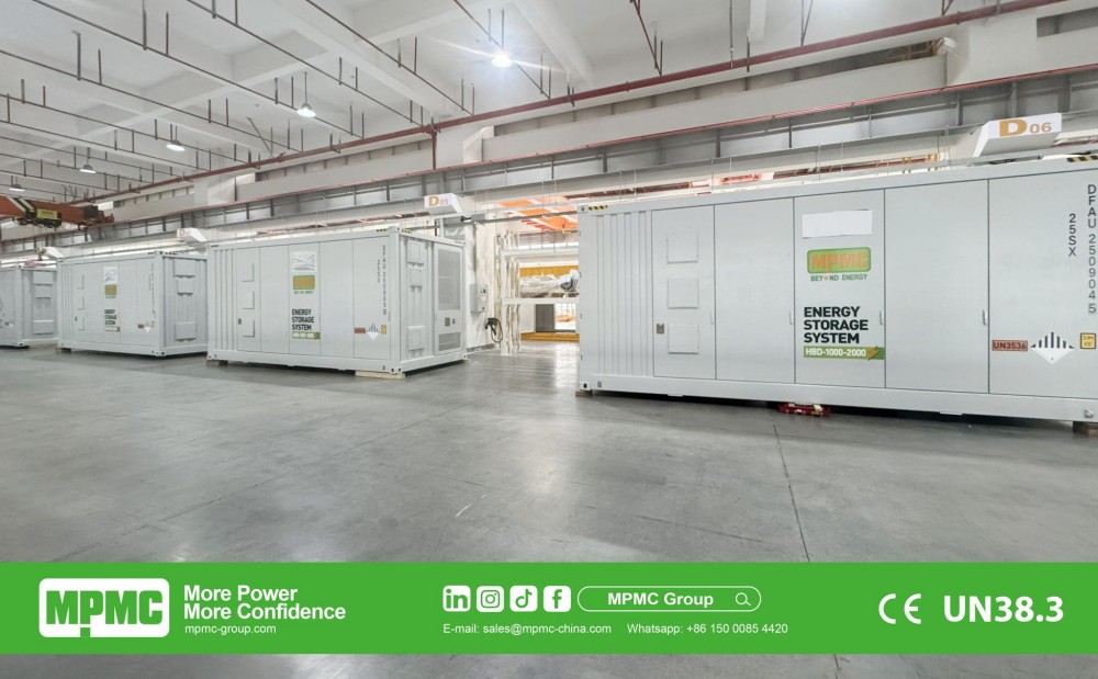 MPMC 8 MWh containerised battery energy storage system — 2 × HBD-500-1000 and 3 × HBD-1000-2000
What the Storage Is Actually For
| Purpose | What the system must do | What governs the sizing |
|---|---|---|
|
Time shifting |
Store daytime generation for evening delivery |
Energy generated after local demand ends |
|
Curtailment avoidance |
Absorb output that would otherwise be lost |
How often and how deeply export is limited |
|
Ramp smoothing |
Offset rapid changes as cloud passes |
Rate of change rather than total energy |
|
Frequency response |
Respond within the network's required window |
Rated power and response time, not capacity |
|
Firming a delivery commitment |
Deliver an agreed profile regardless of weather |
Worst-case resource period, not the annual average |
Most plants want more than one of these, which is legitimate provided the conflicts are resolved deliberately. Energy discharged for time shifting is not available for frequency response, so the control strategy has to allocate capacity between purposes rather than assume both are met.
Reaching 1 MWh in One Unit or Several
MPMC lists the HBD-250-1000 and HBD-500-1000 both at 1,045 kWh, at 250 kW and 500 kW rated AC power respectively, and the HBD-1000-2000 at 1,125 kW with 2,170 kWh. A DC-coupled variant is listed at 5,015 kWh.
That two models share 1,045 kWh at different power ratings is the most useful fact for a solar project. A plant firming an evening delivery is energy-led and served by the 250 kW variant; one providing ramp smoothing or frequency response is power-led and needs the 500 kW rating at the same stored energy.
AC or DC Coupling Is the Architecture Decision
In an AC-coupled arrangement the array and the storage each convert independently and meet on the busbar. In a DC-coupled arrangement they share conversion equipment, which reduces losses on energy flowing from panels to battery and simplifies control of that path.
MPMC lists DC-coupled variants explicitly within the HBD-A series, including the HBD-DC 410 at 418 kWh and the HBD-DC 5000 at 5,015 kWh, alongside the AC-coupled models. Which suits depends on whether storage is being added to an existing plant or both are built together, and the decision should be recorded because it constrains everything downstream.
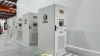
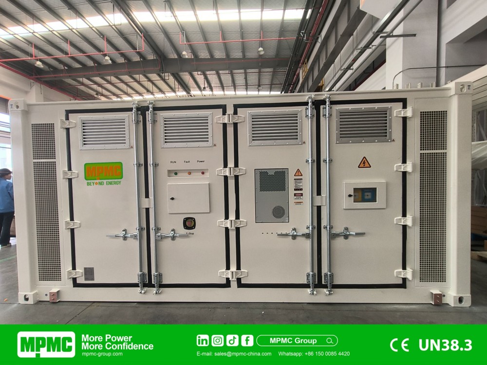 MPMC HBD-500-1000 battery energy storage systems — 10-unit installation
Sizing Against the Worst Resource Period
A plant with storage is sized by its worst period rather than its average. The month with the least irradiation combined with the highest delivery obligation determines the capacity required, and a design optimised for annual averages will fall short in exactly that month.
Three reductions also separate nameplate capacity from delivered energy: depth of discharge, since MPMC rates cycle life at 8,000 cycles at 90% for the HBD-A series; conversion losses; and ambient derating above 45°C. At megawatt-hour scale those reductions are substantial in absolute terms.
Grid Code and the Control Modes Required
A generating plant connected to a network is subject to that network's requirements, which shape the specification as firmly as the resource does. Protection settings, ride-through behaviour, reactive power capability and anti-islanding provisions are normally requested and should be obtained in writing before equipment is ordered.
MPMC lists PQ mode for active and reactive power control, VF mode for independent voltage and frequency control, VSG mode emulating system inertia, black start, grid-forming and reactive power regulation, and publishes grid-connected frequency regulation installations at 8 MWh in the Netherlands and Hungary. Compliance is determined by the local code rather than by the equipment list, and the demonstration obligation should be allocated in the contract.
Conditions at a Generating Site
MPMC lists 314 Ah LFP cells across the HBD-A series with liquid cooling, IP54 system and IP67 battery pack protection, aerosol fire suppression to CE, an operating range of −20°C to +55°C with derating above 45°C and a maximum altitude of 3,000 m, with off-gas detection and a water spray inlet on larger units.
Solar sites are frequently hot, dusty and exposed, which is where the battery temperature warranty condition becomes a design requirement. MPMC states battery box operating temperature must be maintained at 0°C to 25°C with a ±3°C tolerance and humidity at or below 80%, which on such a site depends entirely on the thermal management system.
Expanding a Plant in Phases
Solar projects frequently add storage capacity after the first phase proves the case, and expansion happens by adding units in parallel rather than enlarging one. That preserves the certified baseline and keeps spares common across the site.
What makes it straightforward is what the first phase reserved: switchgear capacity for the eventual unit count, control configuration for more units than phase one contains, and physical space with access and cable routes. MPMC's published 8 MWh Hungarian installation combines two HBD-500-1000 units with three HBD-1000-2000 units, which shows mixed sizes operating within one arrangement.
Solar Plant Storage Checks
● Establish which service the storage is selling before selecting equipment.
● Decide AC or DC coupling and record the reasoning.
● Select on the ratio of rated power to capacity rather than capacity alone.
● Size against the worst resource month combined with the delivery obligation.
● Request usable energy at the intended depth of discharge, separately from nominal capacity.
● Obtain the network operator's requirements in writing before ordering.
● Match required control modes against those supported, including grid-forming.
● Treat the battery temperature condition as a thermal design obligation.
Recent Posts

October 26, 2016
The Most Successful Engineering Contractor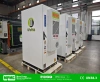


Contact US
Product Information
Quantity
Unit
Piece
Support order samples, customization, wholesale direct, and complete payment. If the product you look for does not have corresponding customized content, pls fill out the form below to contact us, and we will reply ASAP.